We also got a peek into the revolutionary discovery of Hans Christian Oersted—the observation that electricity causes magnetism. This discovery has brought about countless inventions over the past 200 years as it gave birth to the field of electromagnetism. While we’ll explore several of these inventions in later lessons, in this lesson we hope to make sense how a current-carrying wire produces a magnetic field, how you can make a magnet that can be turned on or off, and learn to apply Ampere’s Law to predict the magnetic field around various current-carrying wire configurations.
Imagine a long, straight wire that runs vertically from floor to ceiling. Now imagine this wire surrounded by a platform with a hole drilled in the center through which the wire runs. Let’s now place several compasses on the platform. A side view shows this set-up when no current is in the wire. A top view shows that the compasses do what compasses typically do—point toward the north geographic pole of the Earth.
You decide to pass current through this wire by connecting it to a battery so that the wire carries current toward the ceiling. The side view shown below looks similar except that an arrow has been included to show the direction of the current that is present. The top view, however, now shows that this current is doing something quite remarkable—it is causing the compass needles to realign! Each individual compass needle now points tangent to an imaginary circle that surrounds the wire. Collectively, these needles show that there is a magnetic field that forms a circle around the wire. This is not evidence that the Earth’s field went away, but it is evidence that the current-carrying wire is producing its own magnetic field that is stronger than that of the Earth…and that this field points in a circle.
Replace the compasses with little pieces of iron (called iron filings) and we can see that these filing form circular loops around the wire. This is evidence that the magnetic field created by the current in the wire can be modeled as a series of concentric circles of increasing radius from the wire.
What is remarkable about all this is that we don’t even need a bar magnet to create a magnetic field—all we need is a wire that is carrying current! This means that magnetic fields can be turned on and off by turning current on and off. This will lead us to the invention of the electromagnet—a topic we’ll explore in the next page of this lesson.
The "Field-Finding" Right Hand Rule
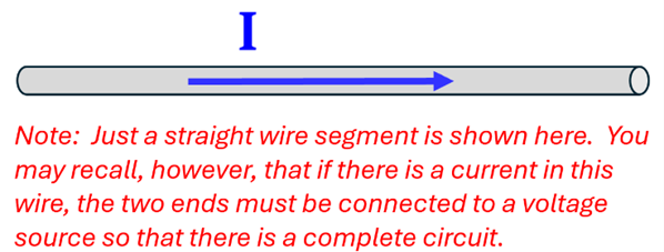
 As we’ve just done, physicists use arrows to show the direction of current in a wire. But how do you use an arrow to show the direction of current in a wire that is traveling exactly toward you…or exactly away from you? Imagine for a moment an actual arrow that is shot from the bow of an archer. What would the archer see if that arrow was traveling away from him? He would see the feathers of the arrow, wouldn’t he? What would he see if the arrow was traveling toward him? He would see the point of the arrow…and then he’d want to get out of there fast! Physicists use this same idea to symbolize the direction of current in a wire.
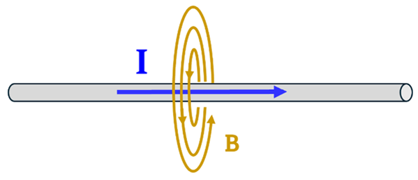
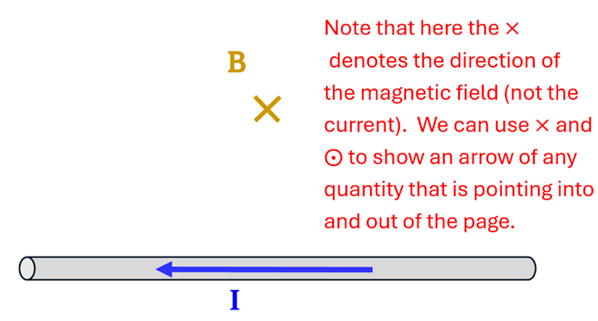
Physics students also use the variable B to represent the magnetic field. For short, sometimes we call the magnetic field the “B-field.”
Both the arrow symbols and the short-hand notation for magnetic field are helpful as we learn to use the “Field-finding” Right Hand Rule. This rule allows us to determine the direction of the magnetic field around a current-carrying wire. Here’s how it works:
- Step 1: Using your right hand, point your thumb in the direction of the current
- Step 2: The fingers of your right hand will automatically curl around the wire in the direction of the B-field
We call this the “Field-finding” Right Hand Rule because it is used to find the direction of the magnetic field when the direction of the current in a wire is known. As a rule of
thumb, you will find this pretty
handy!
Examples
Example 1
Problem: What is the direction of the magnetic field around a current-carrying wire with current directed to the right?
Solution: We’ll use the two-steps of the “Field-finding” Right Hand Rule to determine the direction of the magnetic field (B-field). Point your right thumb in the direction of the current; your fingers will now curl around the wire in the direction of the magnetic field.
Example 2
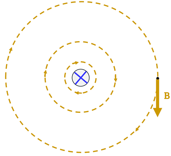
Problem: : Imagine a wire that is carrying current into this page and you are looking end-long down the wire itself. Determine the direction of the magnetic field at a point located to the right of the wire.
Solution: We again apply the “Field-finding” Right Hand Rule. Point your right thumb into the page in the direction of the current. Your fingers will automatically curl around the wire in the direction of the magnetic field. At any point in space, the direction of the magnetic field is the direction that your fingertips are pointing--tangent to the circle at that point. At our location of interest, the tips of our fingers would be pointing downward toward the bottom of the page. Thus, the magnetic field here points downward.
Calculating Magnetic Field Strength for Long, Straight Wire
The “Field-finding” Right Hand Rule helps use find the direction of the field around a long, straight current-carrying wire. But how could we find the magnitude of the B-field at some distance away from the wire? Ampere’s Law is a tool that we’ll explore later in this lesson to derive the equation for the B-field at any location from a current-carrying wire. For now, however, we’ll use the equation that comes from this derivation.
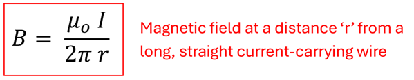
This equation may seem to have come out of thin air. For now, it has. However, we’ll see that the terms in this equation make sense intuitively. Let’s understand each of them.
| Variable |
Description |
Units |
| B |
magnetic field strength |
T (Tesla) |
| I |
Current in wire |
A (Ampere) |
| r |
distance from wire to point where finding magnetic field |
m (meter) |
| uo |
permeability of free space, constant*
uo = 4π x 10-7 Tm/A
|
T m/A |
It makes sense that I, the current in the wire, is in the numerator of the above equation. The more current in our wire the stronger the magnetic field. It should also make sense that r, the distance between the wire and the point where we want to find the magnetic field, falls in the denominator. The bigger this distance, the weaker the magnetic field will be.
While the “Field-finding” Right Hand Rule allowed us to find the direction of the magnetic field at a point from a current-carrying wire, this equation allows us to find the magnitude of this magnetic field. Let’s apply both in a couple additional examples.
Example 3
Problem: Determine the magnitude and direction of the magnetic field at point P located 20.0 cm above a long wire carrying 3.0 A of current to the left.
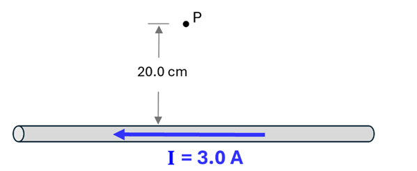
Solution: Begin by applying the “Field-finding” Right Hand Rule to determine the direction of the field at point P. Pointing your right thumb in the leftward direction, your fingers will curl around the wire in the direction of the B-field. You will notice that, at a point directly above the wire and in the plane of the page, your fingertips are pointing into the page. We’ll use an “x” to denote that the field points into the page at this location.
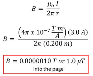
To find the magnitude of the B-field, we’ll apply our equation and make the necessary substitutions:
Example 4
Problem: Determine the magnitude and direction of the magnetic field at point P located 10.0 cm above the midpoint of two parallel current carrying wires that are 20.0 cm apart. Assume each wire carries 5.0 A of current in the direction shown.
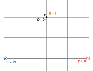
Solution: : In this problem, each of the two currents will contribute to the magnetic field at point P. Since magnetic fields are vector quantities, we’ll need to find the magnitude and direction of the B-field at point P due to each wire and then add these like vectors.
Let’s begin by calculating the magnitude of the field due to either one of these wires. Using the Pythagorean Theorem, we determine the distance that each wire is from point P to be 14.1 cm (or. 0.141 m). Using our B-field equation, we can determine the magnitude of the magnetic field at point P due to each one of the wires to be:

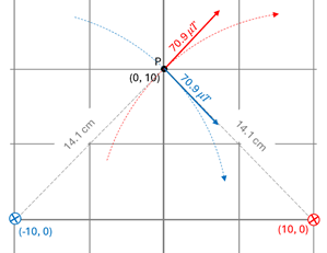
Using the “Field-finding” Right Hand Rule we determine the direction of magnetic field at point P due to each of these to be as shown.
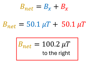
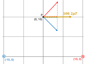
Our last step is to add the two magnetic field vectors—one due to the left wire and one due to the right wire—to find the net magnetic field at point P. As we’ve learned in another chapter, vectors directed at angles to the coordinate axes have components directed along the axes. Trigonometric functions like sine and cosine allow us to resolve those vectors and determine the magnitude of the components. In this example, the y-components are found using the sine (45o). For both the red and blue vectors, the magnitude of the component is B·sin (45o). Thus, the vertical components of these two B vectors are equal; only their direction will differ. Since one points up and the other down, and since their magnitudes are equal, they will cancel each other out. Thus, the net field is just the sum of the two rightward x-components.
Check your Understanding
Use the following questions to assess your understanding. Tap the Check Answer buttons when ready.
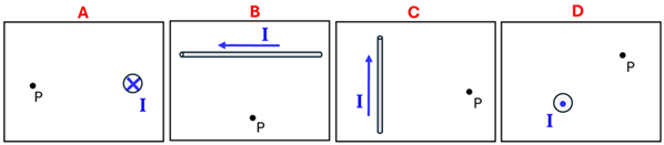
1. Use the “Field-finding” Right Hand Rule to determine the direction of the B-field at point P due to a single current-carrying wire.
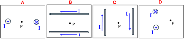
2. Use the “Field-finding” Right Hand Rule to determine the direction of the net B-field at point P due to the combination of current-carrying wires.
3. Calculate the magnitude of the magnetic field at a distance of 2.0 m from a long, straight wire carrying 8.0 A of current.
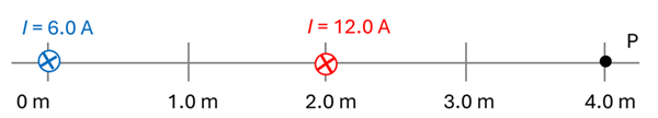
4. Determine the magnitude and direction of the magnetic field at point P due to the two current-carrying wires shown.