Hold down the T key for 3 seconds to activate the audio accessibility mode, at which point you can click the K key to pause and resume audio. Useful for the Check Your Understanding and See Answers.
Lesson 1: Ionic Bonding
Part c: Ionic Compounds
Part 1a:
Electronegativity and Bond Types
Part 1b:
Ions and Ionic Bonds
Part 1c: Ionic Compounds
Ion Ratios and Ion Cards
 We discussed ion ratios in Lesson 1b of Chapter 4. The law of electrical neutrality was used to explain why the Ca2+ ion combines with Cl- ions in a 2:1 ratio but with O2- ions in a 1:1 ratio. There was no discussion of the octet rule; the groundwork for that wasn’t laid until Chapter 5.
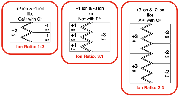
A visual tool known as ion cards was introduced to help conceptualize the ratios by which ions combine. The premise was that every ion can be represented by an ion card. The cation cards are equipped with tabs and the anion cards are equipped with notches. The tabs fits into the notches. The number of notches or tabs is equal to the charge. Fitting the tabs of the cation card into the notches of the anion card is equivalent to forming a compound. Compound formation must be done with the proper ratio of cation to anion. That ratio results in all notches being occupied by tabs and all tabs being fit into notches.

The tool allows one to see why specific ion ratios are required by a cation and an anion. However, ion cards do not approach the topic of ion ratios at a particulate level. Explanations in Chemistry usually involve particles – atoms, molecules, electrons, protons, etc. And when it comes to ion ratios for ionic compounds, the particulate level explanation focuses on electrons. We now know enough to explain ion ratios at the particulate level. It’s time to zoom in.
Electron Dot Diagrams
As we learned in Lesson 1b, ionic compounds are formed by the transfer of one or more electrons from the metal to the nonmetal. The number of electrons that transfer and whether the atom gives or receives the electron(s) is determined by the number of valence shell electrons in the atom. All main group elements find stability in having a full set of s and p orbitals in their outer shell. Put another way, main group elements seek to assume the electron configuration of a noble gas. Main group metals, which typically begin the electron transfer process with one to three valence shell electrons, will lose these electrons. This clears out its valence shell. The metal ion acquires the electron configuration of the noble gas in the previous row of the periodic table. Nonmetals typically begin the electron transfer process with five to seven valence shell electrons. These atoms will gain enough electrons to acquire eight valence shell electrons.
Ion ratios are determined by this principle. Electron dot diagrams are a great conceptual tool for demonstrating the ion ratios. A dot diagram represents a valence shell electron by a dot. The elemental symbol represents the atom. The dot diagrams for period 3 metals and nonmetals are shown below.

 For metals Na, Mg, and Al, the dots are like tabs on ion cards. We can think of nonmetals as having shortages of dots. There are holes or octet vacancies that need to be filled in with electrons. The dot diagrams for the three nonmetals are redrawn at the right. The vacancies are represented by hollow circles. These circles are like notches on ion cards.
 Electrons transfer from the metal to the nonmetal. Each becomes an ion. If the valence shell of the metal empties itself of electrons, and if all the vacancies on the nonmetal fill with electrons, then both ions become electronically stable and an ionic compound is formed. For this to happen, the ion ratio must be correct. Consider the ionic compound formed between sodium and sulfur atoms. The sodium atom has one electron to transfer and the sulfur atom has two vacancies. There must be two sodium atoms involved, providing one electron each, for a sulfur ion to become electronically stable. And so, sodium and sulfur form an ionic compound with a 2:1 ion ratio. Sodium sulfide has the formula Na2S.
 Now let’s consider a magnesium and a chloride atom. Magnesium has two electrons to share. A chlorine atom has a single vacancy. These ions won’t combine with a 1:1 ion ratio. There must be two chlorine atoms available, each with a single octet vacancy, for a magnesium ion to become electronically stable. Magnesium and chlorine form an ionic compound with a 1:2 ion ratio. Magnesium chloride has the formula MgCl2.
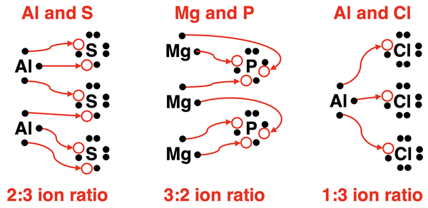
This same electron transfer logic can be applied to any situation involving main group metals and nonmetals. The ionic compounds will form with an ion ratio that satisfies both the metal and the nonmetal’s need to acquire a stable octet of valence shell electrons. As shown below, aluminum and sulfur atoms will combine with a 2:3 ion ratio to form Al2S3. Magnesium and phosphorus atoms will combine with a 3:2 ion ratio to form Mg3P2. And aluminum and chlorine atoms will combine with a 1:3 ion ratio to form AlCl3.

It is important to note that in the above discussion pertains to particles. It’s about electrons and the atoms that will transfer and receive them. It’s about an atom acquiring a stable outermost shell of 8 electrons. It’s a particulate explanation. There no tabs and notches on an ion card. There’s no crisscross rule. Just particles! A particulate view of nature is at the heart of most true explanations in Chemistry.
Closest Packed Structures
 The transfer of electrons between the metal and the nonmetal produces oppositely charged ions. It is the attraction of these oppositely charged ions that result in an ionic compound. As we discussed in Chapter 4, ionic compounds are not like molecular compounds. When we observe molecular compounds at the particle level, we see molecules. A sample of water (a molecular compound) is composed of molecules of water. For ionic compounds, there is no such thing as a stand-alone molecule. A sample of sodium chloride (an ionic compound) is composed of a lattice of sodium and chloride ions that are held tightly together. A lattice, or crystal lattice, is a highly organized arrangement of ions that repeats itself throughout the sample.
The sodium and chloride ions of sodium chloride are held in the crystal lattice by electrostatic forces of attraction. Opposite charges attract. Like all electrostatic forces, the attractions become stronger as the distance between charged ions decreases. As such, an ionic compound can maximize its stability by packing themselves together as closely as possible.
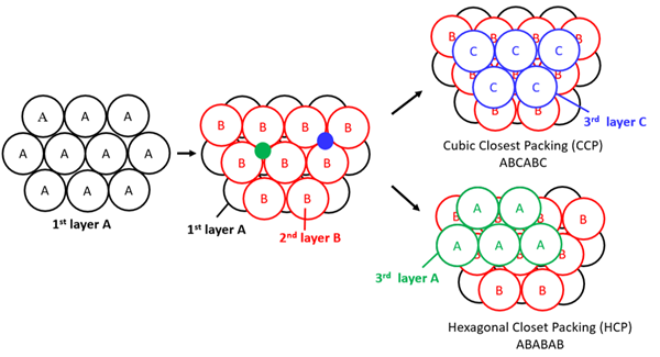
The two most common close packing structures are hexagonal closest packed (hcp) and cubic closest packed (ccp). These packing structures are often modeled by assuming that the particles are solid spheres. Imagine layering a collection of spheres together in an alternating manner such that they fit together as closely as possible. This is Layer A in the diagram below. Notice the holes or spaces located between any three adjacent spheres. These are called trigonal holes. For a closest packed structure, the spheres of the next layer are placed on top of half of these holes in alternating fashion as shown in the middle portion of the diagram below. This is layer B. Just like layer A, there are a collection of trigonal holes formed by layer B. Once more, the spheres of the third layer will be placed above one-half of these holes. But there are two ways to do it. One way it to place the spheres directly above the spheres of layer A, covering one-half of the trigonal holes. This results in a hexagonal closest packed lattice structure. But the other way is to cover the other half of the trigonal holes offset from the spheres of layer A. This results in a cubic closest packed lattice structure.

Image Source: Wikimedia Commons
The vertical layering of a hexagonal closest packed structure is referred to as ABABAB layering. The spheres of the third and fifth layer are directly above the spheres of the first layer. We refer to the layering in a cubic closest packed structure as ABCABC layering. The spheres of the fourth layer are directly above the spheres of the first layer. The spheres of the fifth layer are directly above the spheres of the second layer. And the spheres of the sixth layer are directly above the spheres of the third layer.
Filling in the Holes
 For nearly any crystal lattice that uses a closest packed structure, the larger of the two ions is the one that closest packs. As the larger ions form layer after layer, there are holes left between layers of atoms. The smaller ion will occupy these holes. We discussed trigonal holes earlier. These are holes formed within a single layer between three ions. Trigonal holes are generally too small to accommodate the smaller ion. In closest packed structures, a tetrahedral hole is formed between two layers when an ion of the top layer is placed on top of a trigonal hole formed in the lower layer. The tetrahedral hole is 0.225 times the radius of the larger ion. Octahedral holes are formed by six atoms. The size of an octahedral hole is 0.414 times the radius of the larger ion. Octahedral holes are nearly twice the size of a tetrahedral hole.
Chloride ions are larger than sodium ions. In sodium chloride, the chloride ions form a cubic closest packed structure, leaving a collection of tetrahedral and octahedral holes. The octahedral holes are the perfect size for fitting the sodium ions. By closest packing the larger ions and allowing the smaller ions to fit into the holes, the ions of an ionic solid utilize the three-dimensional space as efficiently as possible. This minimizes the distance between the ions and strengthens the electrostatic force. The strategy provides the most stable lattice structure that is achievable.
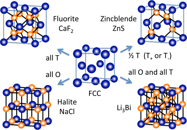
The closest packed structure that is used by an ionic compound and the manner in which the smaller ions fit into the structure depends upon the relative size of the ions and the ion ratio. The diagram below shows the arrangement of the positive and negative ions for four ionic compounds utilizing a cubic closest packed structure. The repeating unit of the lattice structure, referred to as the unit cell, is shown. The blue spheres represent the larger ions. The smaller ion is occupying only the tetrahedral holes (T), only the octahedral holes (O), or both the octahedral and tetrahedral holes.

Image Source: Wikimedia Commons
A closest packed structure works well for sodium chloride and many other ionic compounds. But what happens if the ions are about the same size and the smaller ion can’t fit into the holes? In such cases, the optimal structure is not a closest packed  structure. But it is still a lattice structure with a highly organized array of ions that repeat themselves regularly throughout the sample. A body-centered cubic (bcc) structure is one example of a non-closest packed structure that is still a relatively efficient means of organizing the ions. The packing structure resembles that of hexagonal closest packed with ABABAB vertical layering. It differs from hcp packing in that the ions in each layer are not close packed. That is, the ions within the same layer do not touch each other on their edges. This leaves larger tetrahedral and octahedral holes to fit the second ion into. This is just one of several packing alternatives to hexagonal closest packed and cubic closest packed lattices.
Image Source: Wikimedia Commons
Packing and Properties of Ionic Compounds
The properties of ionic compounds was detailed in Lesson 1a of Chapter 4. Ionic compounds are known for having high melting points and boiling points, being solids at room temperature, having a crystalline nature, and displaying the properties of being hard and brittle. These properties are attributed to the fact that ions within an ionic compound organize themselves into a lattice structure. The more closely packed that the ions are within the lattice structure, the more pronounced that these properties become. Increased packing efficiency leads to stronger forces between ions. This in turn results in increased hardness, higher melting points, and lower solubility. As we’ve seen quite regularly in our Chemistry Tutorial, macroscopic properties can be explained at the particle level.
Before You Leave
- The Check Your Understanding section below include questions with answers and explanations. It provides a great chance to self-assess your understanding.
Check Your Understanding
Use the following questions to assess your understanding. Tap the Check Answer buttons when ready.
1. Predict the cation-to-anion ratio for the following ionic compounds:
- barium phosphide
- aluminum oxide
- potassium nitride
2. Use electron dot diagrams to show the electron transfer between the metal and the nonmetal in the following ionic compounds:
- sodium phosphide
- calcium chloride
- strontium phosphide