Electricity: Electric Field, Potential, and Capacitance
Electrical Energy and Capacitors: Problem Set Overview
There are nine ready-to-use problem sets on the topic of Electrical Energy and Capacitors that are not reliant upon calculus. There are another six problem sets that are calculus-based. Most problems are multi-part problems requiring an extensive analysis. The problems target your ability to use the concepts of electric field, electric potential, electric potential energy, and electric capacitance to solve problems related to the interaction of charges with electrical fields.
Electric Fields
Fields of different types are all around us and are responsible for the behavior of matter/energy over time. A field is a physical quantity that has a value at each point in space. Some examples of fields:
- A source of heat creates a temperature field around it.
- A sink of heat creates a temperature field around it.
- A source of mass creates a gravitational field around it.
- A source of charge creates an electric field around it.
- A source of magnetism creates a magnetic field around it.
A certain characteristic of matter/energy reacts to these fields.
- Molecules can change their kinetic energy when placed in a temperature field.
- The physical characteristic of having mass means an object will experience a force when placed in a gravitational field.
- The physical characteristic of being charged means an object will experience a force when placed in an electric field.
- The physical characteristic of being magnetic means an object will experience a force when placed in a magnetic field.
- The physical characteristic of being a moving charge means an object will experience an electromagentic force when placed in a magnetic field.
- The physical characteristic of having electron spin aligned means an object will experience an electromagentic force when placed in a magnetic field.
Due to their familiarity and similarity, we will begin by considering the gravitational field and the electric field which are both vector fields.
Any mass in the universe sets up a gravity field around it and any charged object sets up an electric field around it. Therefore, any object having mass will feel a force in the gravity field and any charged object or object able to be polarized will feel a force in an electric field.
These fields can be represented visually by lines with arrows indicating the direction of force on an object placed in the field as shown below. By convention the direction of the arrow in an electric field is determined by the direction of the force on a positive charge.
The field can be calculated by determining the force per unit of mass,
m, or unit of charge,
q, placed in the field. The gravity field value would be
and the electric field value would be
Diagrams of a single object experiencing a force in a field created by a single mass and a single charge.
Using Newton’s Universal Law of Gravity for
Fg, the gravity field value would be
and using Coulomb’s Law for
Fe, the Electric field value would
where
M and
Q are the physical characteristics of the objects creating the fields.
Analysis of Point Charges
 A point charge can be a single object of Charge, Q. The object could also be a sphere or hollow shell of many charges that are distributed in different ways. If the object is conductive all the charges adding up to charge, Q, are spread out on the outer surface. If the object is not conductive the charge could be spread throughout the object in various ways. No matter how the charge is distributed the electric field, E, outside the object can be determined using the equation,

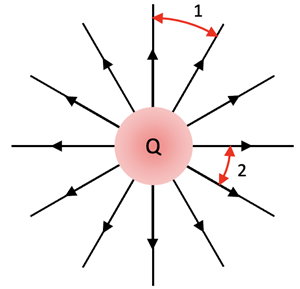
and its electric field lines will be radially configured as shown at right if the object is positive.
The radial lines have large distances between them as you get farther away from the center. This is an indication that the field is weaker. The comparison of spacing between E-field lines can be used to compare the strength of the field at various locations around a charged object. For example, Position 1 is at a weaker field location than Position 2.
When there are multiple E-Field sources in a region, the overall E-Field is the vector sum of E-fields from all sources. This is called The Principle of Superposition. The E-fields of all individual charges is calculated at a specific point and then replaced with the vector sum of these E-fields to get the overall E-field at this point.
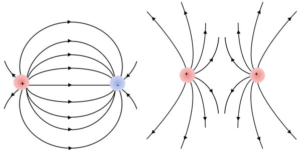
The diagrams below show the typical electric field line patterns that are obtained with 2 Point Charges.
Constant Electric Field
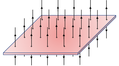
The value of E-fields created by a small number of separate charges is minimal due to the variable spacing of the field lines which means the magnitude of the field is different as you go from one position to another surrounding the charges. A valuable E-field would be one that was constant over a large area. This kind of E-field can be created by a thin, conductive plate uniformly charged as shown below.

The field lines would look like the following:
Gauss’s Law
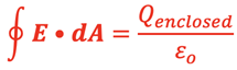
and calculus can be used to show that the E-field on either side of a plate filled with total charge, Qenclosed, would give the following result for the field at every position near the plate:
Flat, thin plate E-field:
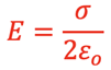
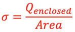
where εo is the permittivity of free space with a value of 8.85418782 x 10⁻¹² farads/meter and σ is the charge density on the surface:
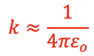
The permittivity is a measure of how dense of an electric field is “permitted” to form around an electric charge. It is related to the k in Coulomb’s Law as follows:
Two parallel plates close together of opposite charge Q and -Q, would produce a field of twice the magntiude of a single plate as shown below.
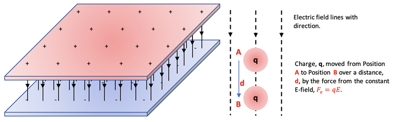
Two flat, thin parallel plates of opposite charge E-field:

since the vector sum of each plate’s E-field adds between the plates and subtracts outside the plates. This electromechanical device is called a capacitor and one of its primary duties is to store charge, and therefore energy, in DC circuits.
Electric Potential Energy in Constant E-field:
As with the gravitational force the electric force can do work on a charged object as shown at right:

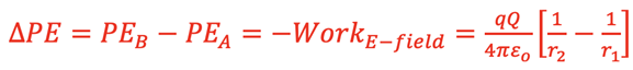
The change in Potential Energy of the charge produced by moving in the direction of the field can be written as:

and substituting from above gives

Electric Potential Energy in E-field around a Point Charge
Consider a charge Q acting as a point charge and creating an electric field in the surrounding space.
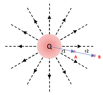
The electric force can do work on a charged object, q, in the field surrounding a Point Charge as shown at right. The issue here is that the E-field created by the charge, Q, is not constant and has to be evaluated using calculus. The work done by the E-field on the moving charge from A to B is the following:

The result of the integration is the following:
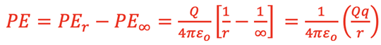
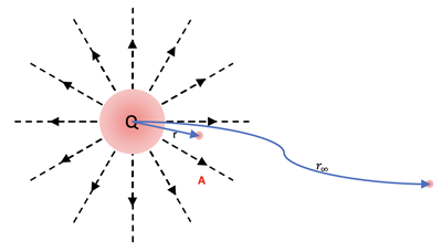
The general expression for the Potential Energy of a charge, q, a distance, r, from the center of a charge, Q, is determined as if the charge was moved by an outside force from a position of ∞:
Electric Potential
In dealing with charged objects it is valuable to work with the idea of Electric Potential Energy per Charge at a point in space in the Electric Field. The outcome of this ratio is that a relatively small charge at that position is not a factor as to the Potential of the field just like a relatively small charge at that position does not significantly affect the Electric Field. The concept of

is called
Electric Potential,
V. The
Difference in Electric Potential between 2 points in an Electric Field is then:
SI unit: Volts = J/C
Electric Potential for a Point Charge
 For a position at distance, r, from the center of a point charge, Q, the Electric Potential at that point can be determined by considering moving the point charge, q, in from ∞.

Electric Potential between Parallel Plates:
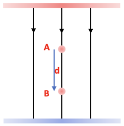 When moving a charge, q, a distance, d, between parallel plates from Position A to Position B and since PEA > PEB the result is the following:
Equipotential Lines
 Lines can be added to Electric Field diagrams that connect points of equal Electric Potential. This is useful to determine whether the Electric Potential Energy increases, decreases, or remains the same when a charge changes position. The single Point Charge Electric Field diagram is shown at right with blue circles added such that each line represents a set of positions of equal Electric Potential. These are called EquiPotential lines.
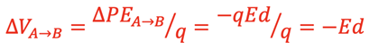
The Equipotential Lines for a constant Electric Field between parallel plates are shown as blue lines below.
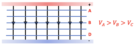
The Equipotential Lines for an Electric Field created by opposite charges are shown as blue lines below.
Considerations when analyzing EquiPotential Lines:
- They are perpendicular to electric field lines since the value of the field does not change anywhere on the line.
- An outside force does positive work to move a positive charge against the field, say from Line C to Line A in the diagrams above, thereby increasing the Potential Energy of the charge and the Electric Potential at the charge’s new position in the field.
- An outside force does negative work to move a positive charge with the field, say from Line A to Line C in the diagrams above, thereby decreasing the Potential Energy of the charge and the Electric Potential at the charge’s new position in the field.
- An outside force does no work to move a positive charge perpendicular to the field, say from one position on Line B to another position on Line B in the diagrams above, thereby not changing the Potential Energy of the charge or the Electric Potential at the charge’s new position in the field.
The Capacitor
Characteristics:
- Generally made of 2 parallel metal plates.
- Made close enough together compared to the dimensions of the plates so that the E-field between the plates is constant.
- When hooked up to a voltage source as shown below the capacitor will become charged over time ending with one positive plate and one negative plate having the same potential difference,
 , as the voltage source.
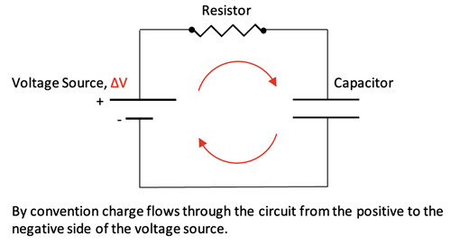
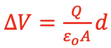
- The E-field set up between the plates is

- The E-field set up between the plates stores Electric Potential Energy.
Capacitance of a Capacitor:
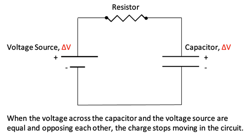
Charge stops flowing into and out of the plates of a capacitor when the Potential difference between the voltage source positive plate and the capacitor positive plate is equal to 0, and similarly the Potential difference between the voltage source negative plate and the capacitor negative plate is equal to 0.
After charging the following relationships for the capacitor are then established:

Substituting Eqn 2 into Eqn 1 gives

and then substituting Eqn 3 in gives
and finally rearranging gives

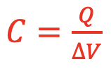
The amount of charge, Q, able to be stored in a capacitor for a given Potential difference, ∆V, depends on the physical characteristics of the capacitor as shown by the left side of the previous equation. This is called the capacitance, C, of the capacitor:

The relationship between Q, C, and ∆V is therefore the following:

Energy Stored in a Capacitor
 Work is required to store positive and negative charges on the plates of a capacitor, thereby storing Potential Energy in the E-field between the capacitor plates.
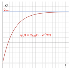
A graph of the charge building up on the plates, Q, versus time is shown at right. Below that is a graph of ∆V versus Q as the capacitor becomes fully charged.
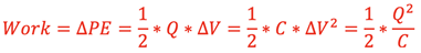
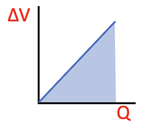 The bottom graph shows that as the charge, Q, builds up on the plates the Potential difference between the plates, ∆V, increases at a linear rate. The work done, and therefore the Potential Energy stored, is the area below the line. It can be represented 3 different ways using previous results:
Dielectric in a Capacitor:
A dielectric is an electrical insulator that can be polarized when placed in an E-field. When the dielectric material is sandwiched between 2 parallel plates as shown below right an additional, smaller E-field created by the polarized dielectric molecules is set up between the plates pointing in the opposite direction of the original E-field.
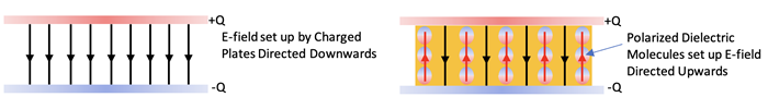
The vector sum of the 2 E-fields results in a smaller overall E-field between the plates. This reduces the voltage between the plates by a factor of K, where K > 1.
Without further charging and with the dielectric in place the capacitance would become
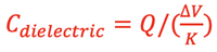
This would result in a capacitance of

since
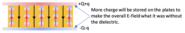
If the voltage source is charging with the dielectric in place more charge will be forced onto each plate as shown below until the voltage between the plates is equal to the source voltage, thereby storing more charge in the capacitor.

Equation Summary
Habits of an Effective Problem-Solver
An effective problem solver by habit approaches a physics problem in a manner that reflects a collection of disciplined habits. While not every effective problem solver employs the same approach, they all have habits which they share in common. These habits are described briefly here. Effective problem-solvers ...
- ...read the problem carefully and develops a mental picture of the physical situation. If needed, they sketch a simple diagram of the physical situation to help visualize it.
- ...identify the known and unknown quantities in an organized manner, often times recording them on the diagram itself. They equate given values to the symbols used to represent the corresponding quantity (e.g., F = 0.025 N, E = 4.50x10⁻⁶ N/C, q = ???).
- ...plot a strategy for solving for the unknown quantity. The strategy will typically center around the use of physics equations and is heavily dependent upon an understanding of physics principles.
- ...identify the appropriate formula(s) to use, often times writing them down. Where needed, they perform the needed conversion of quantities into the proper unit.
- ...perform substitutions and algebraic manipulations in order to solve for the unknown quantity.
Read more...